Citation
A.R. Harris, J. Bellis, N. Khalilgharibi, T. Wyatt, B. Baum, A.J. Kabla and G.T. Charras
Nature Protocols 8:2516–2530 (2013)
Abstract
Abstract
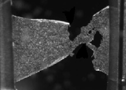
Cell monolayers line most of the surfaces and cavities in the human body. During development and normal physiology, monolayers sustain, detect and generate mechanical stresses, yet little is known about their mechanical properties. We describe a cell culture and mechanical testing protocol for generating freely suspended cell monolayers and examining their mechanical and biological response to uniaxial stretch. Cells are cultured on temporary collagen scaffolds polymerized between two parallel glass capillaries. Once cells form a monolayer covering the collagen and the capillaries, the scaffold is removed with collagenase, leaving the monolayer suspended between the test rods. The suspended monolayers are subjected to stretching by prying the capillaries apart with a micromanipulator. The applied force can be measured for the characterization of monolayer mechanics. Monolayers can be imaged with standard optical microscopy to examine changes in cell morphology and subcellular organization concomitant with stretch. The entire preparation and testing protocol requires 3-4 days.
Figure sample
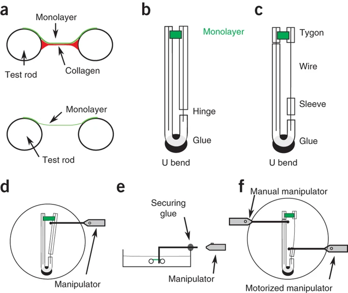
(a) Generating suspended monolayers, a profile view schematic of the device before (top) and after (bottom) removal of the collagen scaffold. The collagen scaffold (red) can be removed by enzymatic digestion, leaving the monolayer (green) freely suspended between the test rods (black circles). (b,c) Schematics of monolayer stretching devices. On both diagrams, the monolayer is represented in green and the glue for fixing the device to the Petri dish is shown in black. (b) Simple device. (c) Force measurement device. (d) Simple device after application of a constant extension, showing the interaction of the prong and manipulator with the test rods. The Petri dish is represented by a circle. (e) The L-shaped wire prong can be detached from the micromanipulator arm and glued to the rim of the Petri dish, enabling application of a constant strain. (f) Position of the micromanipulators and L-shaped wire prongs in force measurements. The Petri dish is represented by a circle.